
Save the file with the simulation results and open the npn_BJT_steady_state.ldev project file. Next from the property editor of the visualizer, choose to plot in log scale. To get the plot shown below, select the "N" attribute in the doping dataset and plot the "Abs" value. The visualizer window will open and the doping profile of the BJT will be plotted.

Once the simulation finishes running, right click on the solver region and visualize the "doping" dataset. The boundary conditions are set up to sweep the collector voltage from 0 to 3 Volts while keeping the base and emitter contacts grounded (V = 0 V). However, if the base-emitter junction is set into forward bias mode by applying a positive voltage in the base contact, majority carriers (electrons) from the emitter entering the base (now minority carriers) get swept into the collector region under the electric field in the space charge region (of the base-collector pn junction) and conduction occurs between the collector-emitter junctions.

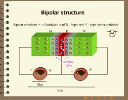
Due of the back-to-back pn junctions, there is no conduction path between the emitter and the collector. The common p region between the two n regions is connected to the third contact, base. There are two back-to-back pn junctions between the emitter and the collector contacts. The schematic of the npn BJT can be seen in the figure below. The file already contains the geometry of the BJT, the doping profile, boundary conditions, and the CHARGE solver region. Open the npn_BJT_ini.ldev project file in CHARGE. Simulation setupĭownload the npn_BJT.ldev and npn_BJT_ini.ldev project files and save them in the same folder. The project file contains the material properties, geometry, and simulation region required to run the example. In the second part of this example we will perform a small-signal analysis to calculate the unity-current-gain cutoff frequency (fT) of the transistor.Ī project file is provided to assist with the application example. In the first part we will perform steady-state simulations to calculate the current-voltage characteristics and the current gain of the BJT. This example describes the simulation of a npn bipolar junction transistor (BJT).


 0 kommentar(er)
